
Page 326 - Manual Oficina Polaris Sportsman 570 2014 a 2016
P. 326
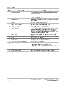
FUEL SYSTEM


                  REF               COMPONENT                                          NOTES
                   q    Instrument Cluster                     For use, settings, pin outs and other related information, see
                                                               the electrical chapter.


                                                               If CAN communication issues are observed exist refer to: CAN
                                                               Troubleshooting, page 11.21
                   w    Ignition Switch                        Refer to the Wiring Diagrams, page  for pinouts for the model
                                                               being serviced.
                   e    Battery                                See: Battery Maintenance, page 2.48

                   r    Starter Motor Solenoid                 See: Starter Solenoid Operation, page 11.34
                   t    Regulator / Rectifier                  See: Voltage Regulator / Rectifier, page 11.39
                   y    Fuse / Relay Box                       The fuse label including location, name and pinout for vehicles
                                                               covered within this service manual are readily available on
                                                               page 1 of the wiring diagram for each harness. Typically the
                                                               fuse / relay information is located to the right of the center of the
                                                               schematic (See Wiring Diagrams, page  ).
                   u    Starter Motor                          See: STARTER SYSTEM TESTING FLOW CHART, page
                                                               11.35
                   i    ECU                                    See: ECU Overview, page 4.21
                   o    Ignition Coil                          See: Ignition Coil / Wire Overview, page 4.35

                   a    Engine Temperature Sensor (ECT)        See: ECT Overview, page 4.45
                   s    Throttle Control                       See:
                                                               • TRS Switch Operation Overview, page 11.25
                                                               • Throttle Release Switch / Throttle Cable Adjustment, page
                                                                 2.32
                                                               • TRS Switch (P/N 2010359), page 11.25

                   d    Diagnostic Connector                   See: Digital Wrench® - Diagnostic Connector, page 4.7


                4.10                                            9926803 R06 - 2014-2016 Sportsman 325 / ETX / 450 HO / 570 Service Manual
                                                                                                © Copyright Polaris Industries Inc.