
Page 348 - Manual Oficina Polaris Sportsman 570 2014 a 2016
P. 348
FUEL SYSTEM
CPS TEST 10.If continuity to ground on the shield is in specification,
inspect harness routing compared to a known good
NOTE vehicle, as well as for accessories that may create
interference. Routing close to ignition cables, stator
The CPS is a sealed, non-serviceable assembly. If fault
code diagnosis indicates a problem with this sensor wires, or HID bulbs and other high voltage
circuit, test as follows: accessories may cause issues.
NOTE
RESISTANCE TEST
It should be noted that dynamic operation is what is
1. Access the CPS connector. read by the ECU, not static testing like resistance
measuring as advised here. While the static tests
2. Disconnect CPS from the main harness connector.
advised will lead to properly diagnosing almost all
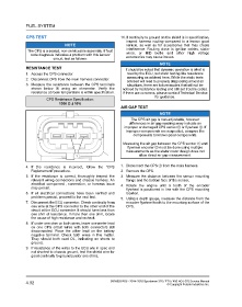
3. Measure the resistance between the CPS terminals situations, there are failure modes that will not be
shown below q using an ohmmeter. Verify the noticed by resistance testing and still set trouble codes.
resistance at room temperature is within specification. If there are concerns, please contact Technical Service
for guidance.
CPS Resistance Specification:
1000 Ω ± 10%
AIR GAP TEST
NOTE
The CPS air gap is non-adjustable, however
differences in air gap readings may indicate an
improper or damaged CPS sensorq or flywheel w. If
improper components are suspected, compare the
components to known good components.
Measuring the air gap between the CPS sensor q and
flywheel encoder w must be done using multiple
measurements as the stator cover design does not
allow direct air gap measurement.
4. If the resistance is incorrect, follow the “CPS 1. Disconnect the CPS q from the main harness.
Replacement” procedure. 2. Remove the CPS.
5. If the resistance is correct, thoroughly inspect the 3. Measure the distance between the sensor mounting
relevant wiring connections and chassis harness. An flange and the bottom face of the sensor.
electrical component , connection, or harness issue 4. Rotate the engine until a tooth of the encoder
may persist.
flywheel is positioned in line with the CPS mounting
6. If all electrical connections have been verified and location.
problems persist, proceed to the next test.
5. Using a depth gauge, measure the distance from the
7. Disconnect the ECU connector. Check continuity from encoder flywheel tooth to the mounting surface of the
one wire at the CPS connector to the other end of the CPS.
circuit at the ECU connector. It should have less than
one ohm of resistance. If more than one ohm, locate
the cause of high resistance and recheck.
8. If under one ohm on both wires, leave one meter lead
on one CPS circuit wires with both connectors still
disconnected. Place the other lead on the battery
negative terminal. Check both wires in this matter.
They should both read OL, indicating no shorts to
ground.
9. If resistance of the wires to the ECU are in spec and
not shorted to chassis ground, test the shield wire for
good continuity to ground (under one ohm).
4.32 9926803 R06 - 2014-2016 Sportsman 325 / ETX / 450 HO / 570 Service Manual
© Copyright Polaris Industries Inc.