
Page 455 - Manual Oficina Polaris RS1 2018 e 2019
P. 455
ELECTRICAL
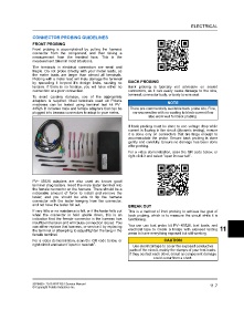
CONNECTOR PROBING GUIDELINES
FRONT PROBING
Front probing is accomplished by pulling the harness
connector from the component, and then taking a
measurement from the terminal face. This is the
measurement taken in most situations.
The terminals in electrical connectors are small and
fragile. Do not probe directly with your meter leads, as
the meter leads are larger than almost all terminals.
Probing with a meter lead will likely damage the terminal
by spreading it beyond it’s design limits, causing no BACK PROBING
tension. If there is no tension, you will have either no Back probing is typically not advisable on sealed
connection or a poor connection. connectors, as it can easily cause damage to the wire,
terminal, connector body, or body to wire seal.
To avoid causing damage, use of the appropriate
adapters is required. Most terminals used on Polaris NOTE
machines can be tested using terminal test kit PV–
43526. It includes male and female adapters that can be There are commercially available back probe kits. Fine,
plugged into banana connectors to adapt to your meter. narrow needles with no coating to block current flow
also work well for back probing.
If back probing must be done to see voltage drop while
current is flowing in the circuit (dynamic testing), ensure
it is done only on connectors that are large enough to
accommodate the probe. Ensure back probing is done
gently and carefully. Ensure no damage has been done
after probing.
For a video demonstration, scan the QR code below, or
right click it and select “open in new tab”.
PV– 43526 adapters are also used as known good
terminal drag testers. Insert the male tester terminal into
the female connector on the harness. There should be a
noticeable amount of force to install and remove the
tester, and you should be able to tip the harness
connector with the tester hanging from the connector,
and not have the tester fall out.
BREAK OUT
If very little or no resistance is felt, or if the tester falls out This is a method of front probing to achieve the goal of
when the connector is held upside down, this is an back probing, which is to measure the circuit while it is
indication that the female connector in the harness has functioning.
insufficient tension and will cause connection issues. You
can either replace that harness, or service it by replacing You can use test probe kit PV– 43526, test leads, and 11
the terminal or attempting to adjust/tighten the tang in the electrical tape to create a bridge with exposed testing
female terminal. areas to have everything exposed but still working.
For a video demonstration, scan the QR code below, or CAUTION
right click it and select “open in new tab”.
Use electrical tape to cover the exposed conductive
parts of the circuit, mainly the clamps of your test leads.
If they contact each other, circuit or component damage
could occur from a short.
9928689 - 2018 RZR RS1 Service Manual 11.7
© Copyright Polaris Industries Inc.