
Page 685 - Manual Oficina Polaris Sportsman 570 2014 a 2016
P. 685
ELECTRICAL
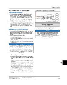
ALL WHEEL DRIVE (AWD) COIL • Test the AWD hub coil using an ohm meter.
OPERATION OVERVIEW
• Key on power is supplied to the AWD hub coil from
terminal 23 in the fuse block, on the RED/GREEN
wire. The AWD hub coil is engaged when ground is
supplied on the BROWN/WHITE circuit for the AWD
hub coil.
• Ground is provided through the ECU, the BROWN/
WHITE circuit terminates at ECU pin 217.
• The ECU must see all required operating conditions
(rpm in range, correct gear range) and an AWD switch
signal to activate. It then communicates with the AWD Hub Coil Resistance:
Instrument Cluster via CAN bus to display the AWD 24 Ω ± 5%
icon.
• Verify that connector pins and grounds are
DIAGNOSING SYSTEM FAILURES undamaged, clean and connect properly.
• Verify the AWD/ADC switch is functional. This can be NOTE
accomplished by seeing if the AWD indicator comes Verify all wires and wiring connections have been
on when the switch is turned on and all AWD criteria tested properly with a known good volt/ohm meter
are met.. before suspecting a component failure. A high
• Verify the AWD/ADC Coil circuit(s). percentage of electrical issues are caused by bad/failed
connections and grounds.
1. Check the DRIVE fuse.
2. Disconnect the AWD/ADC hub coil connector at the
front gear case.
3. Connect the clamp lead of your test light to battery
negative (B-).
NOTE
The BROWN/WHITE (BN/WH) and BROWN/YELLOW
(BN/YE) wires in the AWD/ADC hub coil connector are
grounds, but they are ECU controlled. They will not be
consistent and reliable for either this test or trying to
read voltage with a DVOM. Only use B- at the battery or
a known good chassis ground for testing this and the
ADC circuit.
4. Turn the key on, engine off.
5. Probe the RED/GREEN (RD/GN)wire in terminal C
or D (C is AWD, D is for ADC) on the main harness
side.
If it illuminates, the circuit is verified up to the front
gearcase.
If not, you have an open. Check continuity from the 11
AWD/ADC connector RD/GN in terminal C or D (C
for AWD, D for ADC) back to the DRIVE fuse.
If all checked good, test continuity from the BN/WH
in terminal B of the front gearcase connector to
terminal 17 in the ECU connector (circuit E217) if
the issue is with AWD. If the issue is with ADC,
check the BN/YE back to ECU terminal 49 (circuit
E249).
9926803 R06 - 2014-2016 Sportsman 325 / ETX / 450 HO / 570 Service Manual 11.23
© Copyright Polaris Industries Inc.