
Page 686 - Manual Oficina Polaris Sportsman 570 2014 a 2016
P. 686
ELECTRICAL
ALL WHEEL DRIVE (AWD) SWITCH PIN SYSTEM FUNCTION
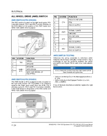
AWD SWITCH (P/N 2010359) 1 PS2 ETC RETURN
The AWD switch is located on the right hand control. PIN 2 ETC PS2
3 provides ground. PIN 4 and PIN 5 provide SIGNAL to 3 PS2 5V SUPPLY
the ECM based on the position of the AWD switch and
AWD / ADC switch when equipped. 4 - -
5 SIGNAL 1 (AWD)
AWD
6 GROUND
7 PS1 RETURN
8 ETC PS1
9 PS1 5V SUPPLY
10 - -
11 SIGNAL 2 (ADC)
ADC
12 RHC 5V SUPPLY
AWD SWITCH TESTING
PIN SYSTEM FUNCTION Reference the wiring schematic to determine which
terminals should have continuity in what position. Use a
1 SIGNAL multimeter to test for continuity between the switch
TRS ground PIN and Signal PIN for each drive mode selector
2 GROUND
switch.
3 GROUND
NOTE
4 AWD / AWD SIGNAL
ETC Use a small pick to disconnect the right hand control
5 AWD / ADC SIGNAL (IF from the main wiring harness.
EQUIPPED)
• Verify no continuity (OL) in the disengaged position. (I.
E. 2X4)
AWD SWITCH (P/N 2010436)
• Verify continuity in the Engaged Position. (i.e. 4x4 ,
The AWD Switch on ETC equipped models it located on ADC, or 4WDC)
the right hand control. PIN 12 provides a 5V reference
signal to the Right hand control from the ECM. PIN 6 If any of the tests listed above tests fail, replace the right
provides a ground. PIN 5 and PIN 11 provide a SIGNAL hand control.
to the ECM based on the position of the AWD switch and
AWD / ADC switch when equipped.
11.24 9926803 R06 - 2014-2016 Sportsman 325 / ETX / 450 HO / 570 Service Manual
© Copyright Polaris Industries Inc.