Page 83 - Manual Oficina Polaris Sportsman 570 2014 a 2016
P. 83

MAINTENANCE


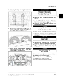
                   8. Rotate the drive clutch until the intake and exhaust               MEASUREMENT
                      cam lobes face away from each other as shown.
                                                                                     Intake Valve Clearance (cold):
                                                                                    .005 ± .002″ (0.125 ± 0.05 mm)
                                                                                    Exhaust Valve Clearance (cold):
                                                                                    .014 ± .002″ (0.350 ± 0.05 mm)
                                                                                                                              2
                                                                         11. Record the results of each measurement for future
                                                                            reference.
                                                                         12.If the valve clearances are out of specification,
                                                                            proceed to “Valve Clearance Adjustment”. See Valve
                                                                            Clearance Check / Adjustment, page 3.68
                                                                         13.If previously removed, reinstall the spark plug. Torque
                                                                            spark plug to specification.

                                                                                             TORQUE
                                                                                          Spark Plug Torque:
                   9. When the cams are at TDC, the I’s on the intake cam           9 ft-lbs (12 Nm)w/o anti-seize
                      sprocket and E’s on the exhaust cam sprocket will be
                      inline with the cylinder head deck as shown.
                                                                         14.Inspect the valve cover seal and replace if necessary.
                                                                         15.Install NEW isolators on the valve cover bolts. Install
                                                                            the valve cover and the four T40 bolts. Torque bolts to
                                                                            specification.

                                                                                             TORQUE
                                                                                          Valve Cover Bolts:
                                                                                           7 ft-lbs (10 Nm)


                                                                         16.Install the spark plug wire. Ensure wire is pushed
                                                                            down all the way so it fully engages the spark plug.
                                                                         17.Install drive belt and outer clutch cover and (8)
                                                                            retaining screws (see PVT System). Torque to
                                                                            specification.
                   10.Measure the valve clearance between the intake and                     TORQUE
                      exhaust lobes and tappets using a feeler gauge.
                      Compare results to the specifications.                          Outer Cover Screws, PVT:
                                                                                           50 in-lbs (5 Nm)


                                                                         18.Connect the negative (-) battery cable to the battery.
                                                                         19.Reinstall the fuel tank and front cab.
                                                                         20.Reinstall the air box cover and PVT ducting.
                                                                         21.Reinstall the side panels, and seats.
                                                                         22.Start the engine to ensure proper operation.


                   9926803 R06 - 2014-2016 Sportsman 325 / ETX / 450 HO / 570 Service Manual                          2.17
                   © Copyright Polaris Industries Inc.
   78   79   80   81   82   83   84   85   86   87   88