
Page 184 - Manual Oficina Polaris RZR XP 1000 17-18
P. 184
ENGINE / COOLING SYSTEM
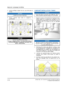
7. Install and finger tighten the two outer M6 bolts y CAMSHAFT INSTALLATION / TIMING
evenly.
NOTICE
NOTICE
If any valve train components were replaced, refer to
Install new cylinder head bolts. Valve Clearance Adjustmentpage 3.81 procedure.
8. Torque cylinder head bolts in sequence to 1. Rotate the engine until the flywheel Top Dead Center
specification. (TDC) mark q is aligned or centered in the
Crankshaft Position Sensor (CPS) mounting hole w.
This places the PTO cylinder at TDC for camshaft
installation.
TORQUE
Cylinder Head Torque Procedure:
Torque in sequenceStep 1: 13 ft-lbs (18 Nm)Step 2: NOTICE
26 ft-lb (35 Nm)Step 3: Additional 180°Step 4: M6 DO NOT use the “V” mark located on the flywheel
bolts: 7 ft-lb (10 Nm)
opposite of the “I” mark. Only the “I” mark should be
used as a TDC reference.
2. Reference the intake and exhaust markings made
during disassembly. If installing new camshafts or if
camshafts were not marked, you can reference the
part number stamped on the end of the shafts and
compare to the electronic parts catalog.
3. Lubricate all camshaft lobes and bearing journal
surfaces with Polaris PS-4 engine oil prior to
installation.
4. Carefully install the camshafts into the cylinder head.
The PTO camshaft lobes t should face out as
shown.
3.76 9928492 R06 - 2017-2018 RZR XP 1000 / XP4 1000 Service Manual
© Copyright Polaris Industries Inc.