
Page 346 - Manual Oficina Polaris RZR 570 13-18
P. 346
FINAL DRIVE
14. Maneuver the rear of the prop shaft rtowards the DISASSEMBLY
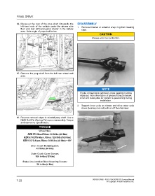
left-hand side of the vehicle under the drivers side 1. Remove internal or external snap ring from bearing
floor and rear left-hand panel divider in the battery caps.
area. Note angle of prop shaft below.
CAUTION
Always wear eye protection.
15. Remove the prop shaft from the left rear wheel well
area.
NOTE
If yoke or bearing is removed, cross bearing must be
replaced. Note orientation of grease fitting and mark
inner and outer yoke for correct re-positioning during
installation.
2. Support inner yoke as shown and drive outer yoke
down (bearing cap out) with a soft face hammer.
16. Reverse removal steps to reinstall prop shaft. Use a
NEW Roll Pin (Spring Pin) upon reassembly. Torque
all fasteners to specification.
TORQUE
Wheel Nuts:
RZR 570 Steel Rims: 36 ft-lbs (49 Nm)
RZR 570 EPS Alum. Rims: 120 ft-lb (163 Nm)
RZR S 570 Alum. Rims: 30 ft-lbs (41 Nm) + 90°
Drive Clutch Retaining Bolt:
47 ft-lbs (64 Nm)
Outer Clutch Cover Screws:
100 in-lbs (12 Nm)
Brake Line Junction Block Mounting Screws:
36 in-lbs (4 Nm)
7.22 9926813 R06 - 2013-2016 RZR 570 Service Manual
© Copyright Polaris Industries Inc.