
Page 566 - Manual_Polaris_RZR_ProXP-20-21
P. 566
ELECTRICAL
COOLING SYSTEM
COOLING FAN DESCRIPTION AND COOLING FAN TESTING
OPERATION The cooling fan circuit can be tested for proper function
The RZR Turbo fan is controlled by the ECU and a solid by using Digital Wrench – Output State Control. From
state driver in the fan motor assembly. this menu, you can turn the cooling fan off and on. If the
cooling fan does not come on when requested:
Power is supplied through a 30 amp fuse to terminal 1 of
the fan connector. 1. Disconnect the harness going to the fan and check
for power and ground on the main harness side using
The ground path for the motor assembly is provided a multimeter.
through terminal 2 of the fan assembly connector.
NOTICE
Terminal 4 of the fan assembly connector runs back to
141, or terminal 41 of ECU connector 1. This provides a When performing this test, Fan Control must be set to
pulse-width modulated ground path that acts as the ON or no voltage will be seen.
control signal for the controller in the fan assembly. This
controls fan speed. The longer the ground path through 2. If power is present, reconnect the fan harness and
the ECU is left on, the faster the fan motor will spin.
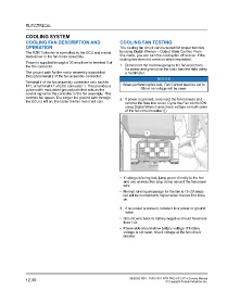
remove the fuse box cover. Cycle the Fan control ON
using Digital Wrench and check voltage on both sides
of the fan circuit breaker q.
• If voltage is being lost, jump power directly to the fan
and use an inductive amp clamp around the fan power
wire.
• Normal running amperage for the fan is 15–20 amps
but will be momentarily higher when the fan first kicks
on.
3. If no power is present, isolate it to a power or ground
issue.
• Ground wire back to battery negative should have less
than 1 Ω.
• Power side should show battery voltage. If battery
voltage is not seen, check voltage at the fan circuit
breaker.
12.30 9930583 R01 - 2020-2021 RZR PRO XP / XP 4 Service Manual
© Copyright Polaris Industries Inc.